A battery management system (BMS) is an electronic system that manages a rechargeable battery (cell or battery pack) by monitoring its state, controlling its load environment and charge-balancing the system, allowing an adaptive rechargeable protocol that can accommodate a variety of various battery types with dynamic adjustment of the protocol to eliminate problems of overcharging, undercharging and having a mix of old and new batteries varying levels of output voltage levels mixed and combined in the field to meet demands.
Ridgetop has experience in the physics-of-failure for various chemistries of batteries and fuel cells, and can apply domain knowledge in advanced diagnostics and prognostics to create a tightly managed and optimized BMS.
Advanced Battery Management System Applications
- Supports various Lithium-Ion chemistry variations
- Allows partially discharged batteries to be combined
- Provides proper and safe call balance to avoid overcharging
- Defective batteries are switched out automatically
- CAN and IVHM diagnostics
Battery Packs and Cell Balancing
The battery pa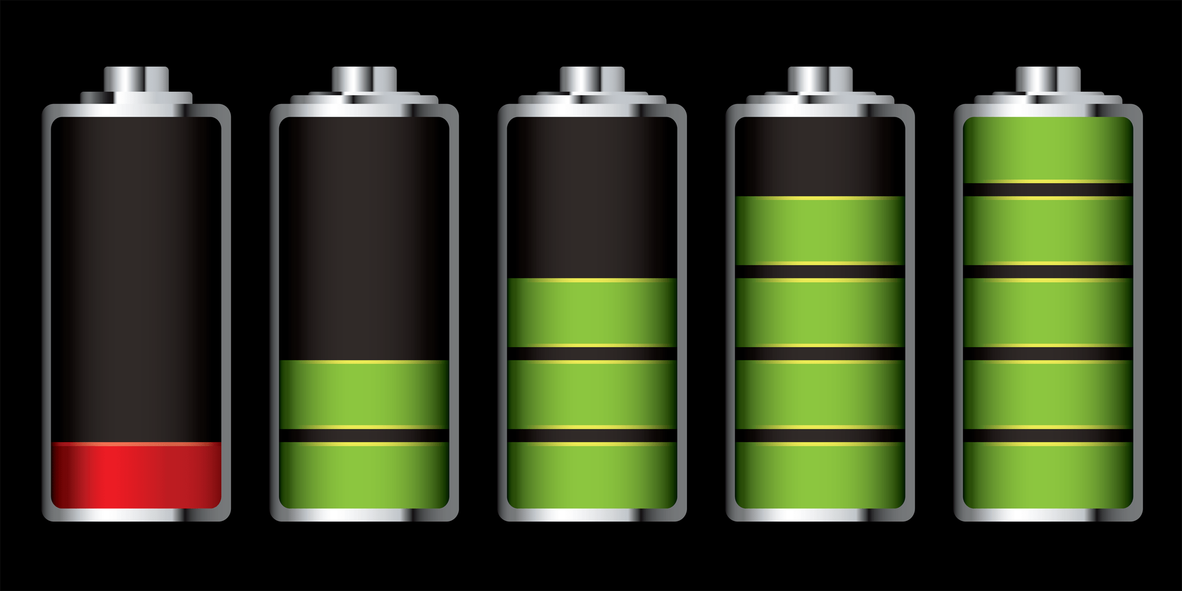 ck incorporated into a BMS will improve the charging efficiency, extend the useful life, and increase overall capacity of rechargeable lithium-ion (Li-ion) battery packs through a principle known as cell balancing. With five different battery types, Nickel Cobalt Aluminum (NCA) , Lithium Iron Phosphate (LFP), Lithium Cobalt Oxide (LCO), Nickel Manganese Cobalt (NMC), and others, there are 20 different combinations of cells possible, all able to be managed by this advanced BMS. Among a stack of Li-ion cells, each battery will be slightly different in its state of charge (SOC) and capacity-to-energy (C/E) mismatch. Under conventional charging methods, all cells are charged (and discharged) at the same current, and the battery pack is limited by its weakest cell.
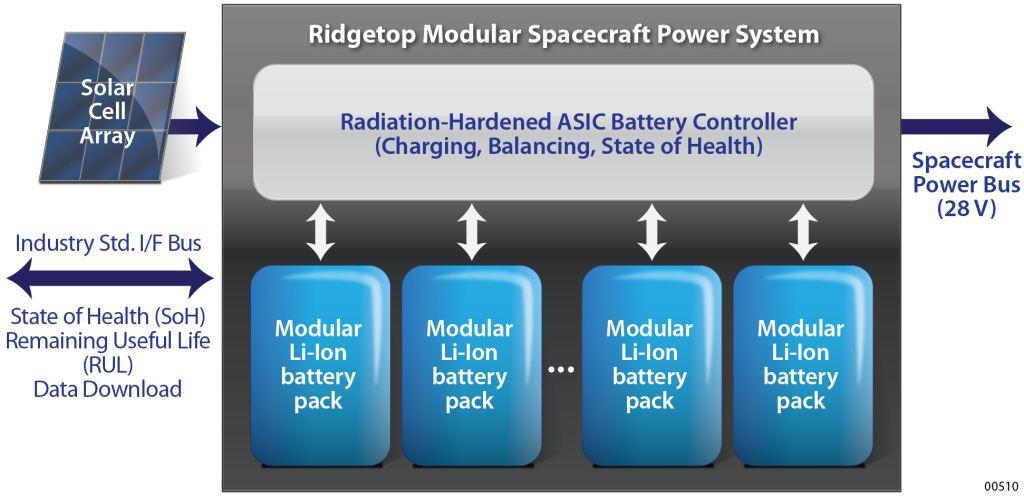
In contrast, Ridgetop has designed systems that are capable of measuring the individual cell voltages of an 8-cell series-connected battery pack. This system is based on a System Control application-specific integrated circuit (ASIC), a solar cell subsystem, and a Li-ion battery subsystem. A simplified diagram of Ridgetop’s Satellite Power Supply System architecture is shown below.
In addition to the battery interface electronics, Ridgetop can provide complete solar cell/battery power subsystems that are very efficient and flexible and will operate in the following modes:
- Satellite power coming from the solar cells
- Battery charging
- Satellite power coming from the batteries
- Combination of power coming from the batteries and the solar cells
- Charging the batteries while the rest of the satellite is receiving power from the solar cells
- Monitoring battery level of charge, charge-leveling between batteries, and state of health
A protection system is self-contained within the BMS and all power lines distributed to various loads should be adequately protected. For spacecraft applications, interfaces and protections are critical. Ground commands, which can override or disable critical protection and reconfiguration circuitry, should be included in a design as a safeguard against failures.
The image below illustrates an example of Ridgetop’s combined solar/battery BMS solution.

The diagram depicts the satellite power system being composed of three subsystems:
- The solar cell subsystem which contains the solar cell array
- The Li-ion battery subsystem which contains the batteries
- The control ASIC (The “brains” of the system)
It maintains the state of he alth of the batteries, the current output of the solar cells, and the 28-volt system power. It can pull all of the power from the solar cells and charge the batteries at the same time if there is enough capacity; or just supply the main power; or supplement the solar cells with battery power; or use the batteries to supply all of the main power to the system.
Relevant BMS Programs from Ridgetop
- NAVSEA MH-60 NiCd Power System for Sonobuoy power — In this case, Ridgetop designed a unique variable addressing scheme for charging and isolating battery strings.
- NAVAIR Program — Ridgetop designed a BMS system for a military program.
- NASA Fuel Cell Program — Ridgetop designed a 48 channel IC for individual cell monitoring. This IC is also suitable for monitoring the cell voltages of battery cells and using the measured data to control the charging and discharging. Ridgetop also designed the embedded controller to control the mixture of chemicals to support polymer electrolyte membrane (PEM) fuel cells.
- Commercial Electric Vehicle (EV) BMS — Working with an automotive partner, Ridgetop designed advanced diagnostic and prognostic capabilities into a complex BMS for an automobile.
Contact us for more information, or download the technical papers below.